Samsung Twin Cooling operating function.
Samsung Twin Cooling operating function.
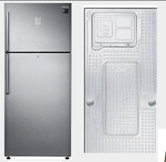
Today we will learn about Samsung Twin Cooling Refrigerator Complete Repair Guide. First of all I will explain about the name and functioning of each part in refrigerator.
1- PCB In latest model two types of PCB or Combo PCB are used one is Main PCB and other is Inverter PCB. Main PCB is the big one which is mounted on the back of the refrigerator with inverter pcb.


All the sensors, fans, step valves, display and heater assembly are connected to the main PCB.
Inverter PCB This PCB is used for the purpose of starting the compressor only. The triggering for compressor start is derived from the main PCB circuit.
Now we will find the fault of the component of each part connected to the main PCB. sensor There are 5 basic sensors available in this refrigerator. of which 2 are in the freezer and 2 are in the fridge and 1 is on the outside of the refrigerator.
1-Freezer Sensor,
2-Freezer Defrost Sensor, 3-Fridge Sensor,
4-Fridge Defrost Sensor and 5-Room Temperature RT Sensor.
The freezer sensor controls the freezer compartment cooling while, the freezer defrost sensor monitors the defrost cycle of the freezer compartment.
fridge sensor monitor fridge temperature and fridge defrost sensor monitor fridge defrost cycle.
The RT sensor is used for sensing outdoor temperature only.
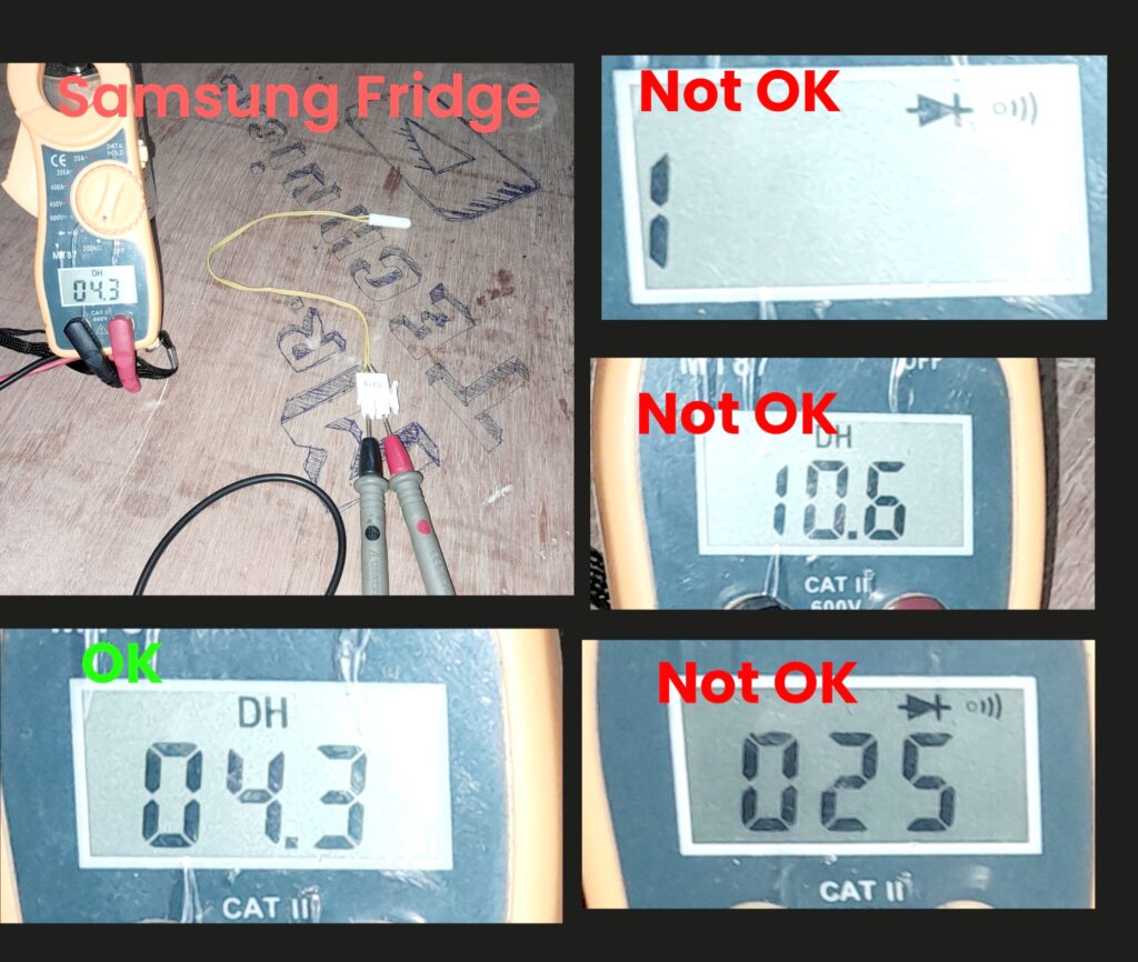
Each sensor shows a value of 4K to 6K ohm at normal roomtemperature.
If the value of any sensor changes to zero or infinity then the main PCB starts displaying the error code related to that sensor.
The next part is the step valve which is attached to the main PCB. The step valve in this model has three openings. One hole is to receive liquid refrigerant from the dryer filter and the other two holes are connected to separate evaporators in the fridge and freezer respectively.
The step valve consists of a DC motor which is rotated by the main PCB to open or close the passage of refrigerant gas. It is checked only by its vibration during the initial power supply.
No other methods are available in the manufacturer data.
Normally the main PCB supplies the DC voltage to the step valve motor.
Closes or opens the freezer and fridge pathways to control the refrigerant flow, depending on the intent of the main PCB.
The next part is the fan motors, in some of these models 3 fan motors are used for cooling purpose. 1 freezer fan motor 2 fridge fan motor 3 condenser fan motor.

Freezer fan only works for freezer cooling.
And fridge fan only work for fridge,

While condenser fan is used to cool the discharge refrigerant flowing through the condenser.
All fans are DC type that use 12V from the main PCB. You can test this externally with a 12V power supply with positive connected to red and negative connected to black.
The white wire is only for sending feedback to the main PCB. If this feedback is not received by the main PCB, an error starts appearing on the display.
The defrosting circuit is a set of parts called defrost heaters, thermal fuses, and bimetal.
All parts are connected in series with each other. If the freezer temperature goes above 72°C during the defrosting cycle, the thermal fuse stops working.
And the bimetal turns on when the freezer temperature drops below 40 degrees Celsius. The defrost heater will only work if the bimetal and fuse are good.
The defrosting circuit receives 230V AC from the main PCB when the refrigerator is operating in cooling mode for more than 8 hours. This means that the defrost cycle starts every 8 hours. If any part is damaged, defrosting will not be complete and cooling in the freezer will be reduced.
Also generates error code for main PCB defrosting failure in some models. Defrosting is easily accomplished by the step valve in the fridge section.
The step valve stops the flow of refrigerant into the refrigerator’s evaporator, which causes the frosting to melt. There is no heater available for this function as there is no need to make ice in this compartment.
read in hindi
Samsung Side by side refrigerator error
gas charging dignose
gas charging dignose in hindi
r290 gas charging video
Inverter compressor testing with multimeter
inverter compressor identification
power supply testing with multimeter